FRC Control System
Control System Basics
- Battery supplies Power to the Robot
- Power originates with a distribution hub or panel (PDH/PDP/AMPD)
- Swerve encoders can be spliced from a single wire.
- Soldering is a way that teams have spliced. You’ll learn later why soldering is considered bad for an FRC environment, but for now, just understand it is a worse solution than others.
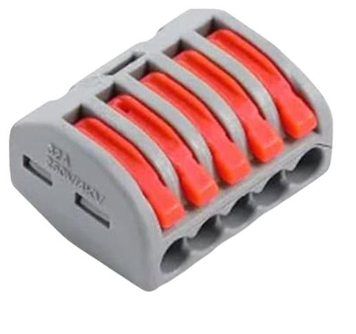
- A 5-port Wago is the most common correct way to accomplish a 4-way splice for encoder wires.
CAN (Controller Area Network)
- CAN can be wired in two different ways:
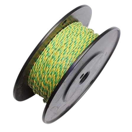
- Daisy-chained: this is the way that CAN is meant to be wired, and it is the most common way that FRC components are wired. CAN wires originate at the Systemcore in one of the CAN bus ports. The wires then go to each component in order, ending at the terminating resistor. One full loop, as mentioned previously, is called a CAN bus.
- Star topology (not recommended): This is the method used to branch the CAN bus by each individual component. This is used by some teams because in a normal CAN bus, if one component loses a connection, they all do.
- With a Star topology, each component has its own individual “CAN bus”. This is not recommended at all in modern FRC, as the introduction of SystemCore allows you to split up CAN buses much further than originally.
- Additionally, a star topology presents many issues as it is NOT AT ALL how CAN is meant to be wired.
- Always place the resistor at the end of each loop. This will be a 120 OHM resistor in a WAGO, or if terminating at a motor with a powerpole adapter board, the Weidmuller connectors may be used.
Specific Electrical Components
Motors
- Motors are the joints of the robot; they control every moving and rotating component on most modern robots. Thus, wiring them is very important. There are two types of motors, brushed and brushless.
- In FRC, all that really needs to be known is that brushed motors aren’t usually used anymore. However, these types of motor can be used in specific applications as well as being offered in the KOP. Outlines of both types will be provided below before the motors most commonly used in FRC are discussed.
- Brushed: Brushed motors have 4 components: The stator, rotor, commutator, and brushes. In this diagram, the rotor can be thought of as the shaft and rotor coils. They are attached to the commutator. The way it works is this: The stator magnets are permanent, and when electrons are passed from the brushes to the commutator to the rotor coils, it produces a magnetic field opposing the one created by the stator magnets’ fields. However, the magnets would usually stop rotating when the fields are in alignment.
- How does this get prevented? The commutator uses a specific pattern of metal to make it so that the field always opposes that of the stator magnets, therefore causing rotation. Brushed motors are most commonly used in cheaper appliances.
- Brushless: Brushless motors are like brushed motors in many ways. They can have an internal or external rotor (the diagram has an internal rotor). What you may notice about the motor is that it has no brushes. How then does it create opposite polarities? This is through an electronic circuit that detects how much the motor rotates.
- This makes for less contact throughout the system and a more precise transmission of power, which is why brushless motors are used throughout the world and especially in FRC.
- Brushed: Brushed motors have 4 components: The stator, rotor, commutator, and brushes. In this diagram, the rotor can be thought of as the shaft and rotor coils. They are attached to the commutator. The way it works is this: The stator magnets are permanent, and when electrons are passed from the brushes to the commutator to the rotor coils, it produces a magnetic field opposing the one created by the stator magnets’ fields. However, the magnets would usually stop rotating when the fields are in alignment.
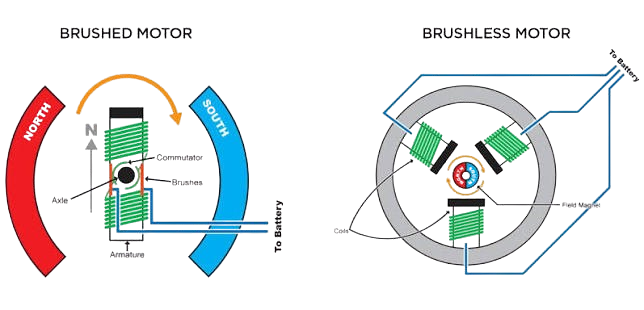
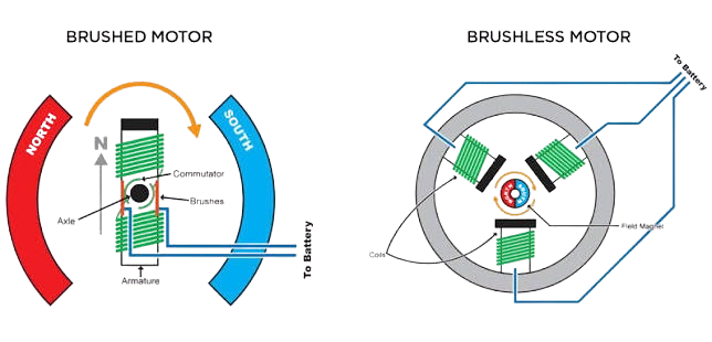
Brushed motor on left, brushless motor on right
Common FRC Motors
WCP's Kraken
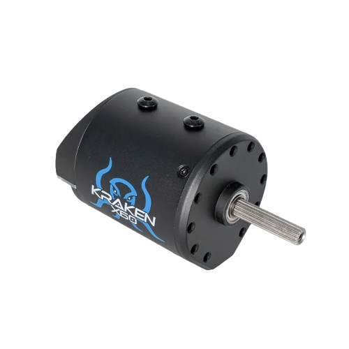
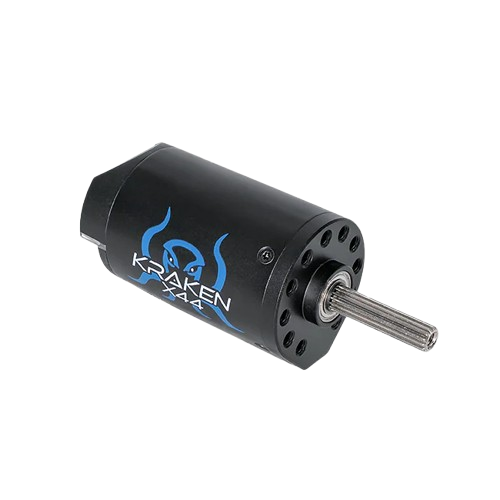
Krakens are arguably the most powerful motor in FRC. There are two types of Krakens- X60 and X44 (For 60 mm and 44 mm Outer Diameter, respectively). * These motors have built-in motor controllers, called TalonFX, which will be discussed in more detail later. They have two screws for cooling ports on the side that can be removed and covered with electrical tape. * For Kraken wiring, there are two ways to go about it, but for both, the CTRE Torque Wrench is a tool that makes the application much better and removes hesitancy due to fear of overtightening bolts.
- You can use the built-in ring terminals. The Kraken comes with them, and with the torque wrench, they’re easy to install. The wiring guide is on the WCP documentation. This may require extra splicing for longer wire runs, but overall, they are a fine solution.
- WCP Powerpole Adapter Boards. This replaces the ring terminals with common FRC connectors: Anderson Powerpole connectors and Molex SL connectors, which will be taught later. One extremely important thing to note is that the screws for these are NOT able to be used for ring terminals. That can severely damage the controller and also cause CAN bus issues. These allow for a continuous run and easy removal of wires, no matter what length wire run is necessary. The non-flipped X60’s also allow for termination using their top Weidmuller connectors as a hub for a 120 Ohm resistor. X60 Board, Flipped X60 Board, X44 Flipped Board
REV's NEOs
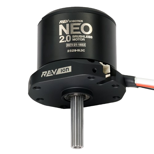
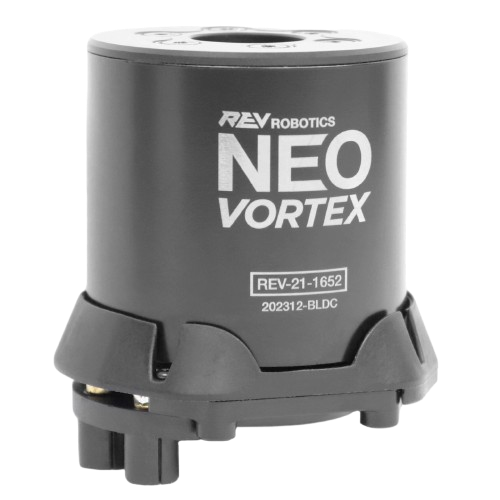
REV's NEO (NEO Vortex and NEO 2.0 best picks for price)

CIMs
- CIM Motors are the only brushed motors seen on this list. They are the motors FIRST uses on their fields and the motors that come with the kitbot. Similar to NEOs, they are controlled with External motor controllers.
Motor Controllers
These are the devices that control the motors and help direct power and signals to each mechanism.
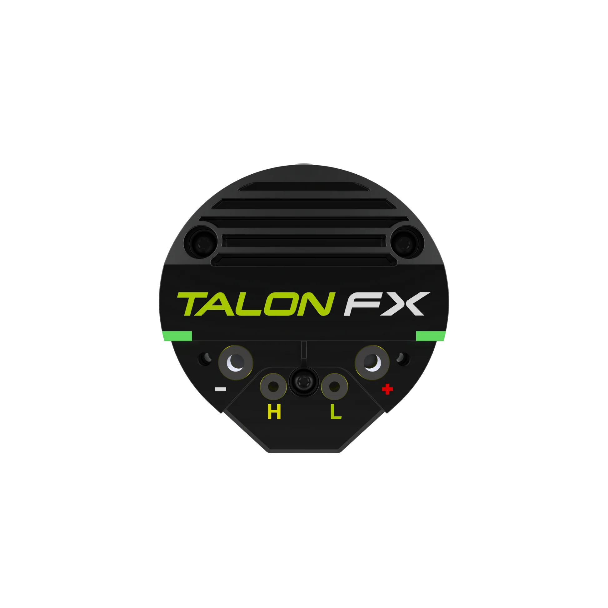
- This is the controller that is integrated into the Kraken’s (both X60 and X44). Talon FX acts as an integrated motor controller, meaning that an external controller that is separately wired is not needed.
- For Kraken X60/X44s, wiring is relatively simple because the controller is integrated in the motor itself. CAN and power directly stem from the motor and can be connected to their appropriate locations.
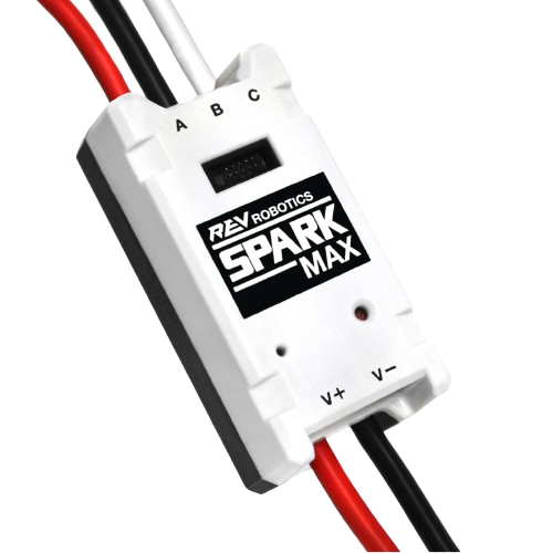
- SparkMAX is often considered the best motor controller for price.
- This is a controller optimized for the NEO brand and works for brushed and brushless motors.
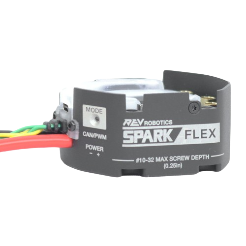
- Spark Flex is a motor controller made for integration with the NEO Vortex.
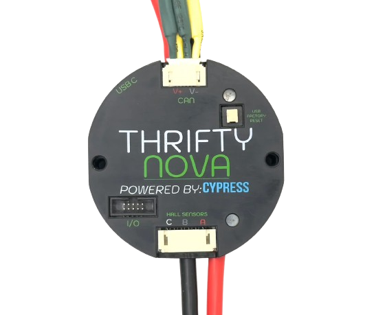
- TTB's Nova is Thrifty Bot’s motor controller option.
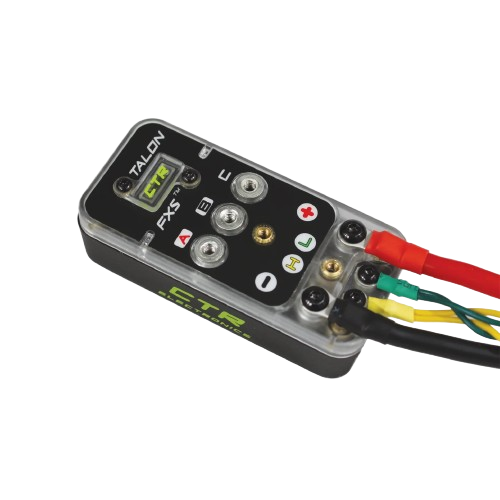
- Talon FXS is optimized for CTRE’s Minion motor and supports CAN FD capabilities. The TalonFXS can also work with other motors, like REV's NEO 1.2 / 2.0 / 550.
Gyroscopes
These allow for the positional accuracy of your robot, as shown on logs. This is important for the autonomous period of your robot in the match, as well as automatic positioning.
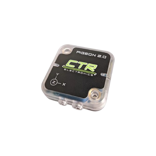
- Pigeon 2.0 is often considered the best quality option.
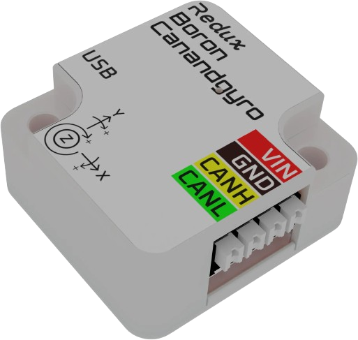
- CANandGyro is a strong price-focused choice.
Power Distribution
Power distribution boards are how power gets around the robot. They can range from complex circuits to simple copper blocks.
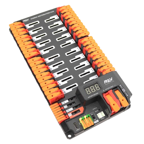
- PDH is often considered the best quality option for teams that want a robust and modern distribution board.
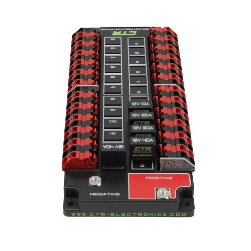
- PDP 2.0 is a strong budget-friendly choice for teams looking for a reliable lower-cost option. The PDP 2.0 also has more ports than the PDH, so if you need more slots, this is the way to go.
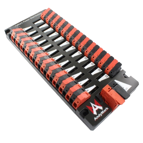
- AndyMark Power Distribution is another common choice that works well for many FRC teams.
Fuses and Breakers
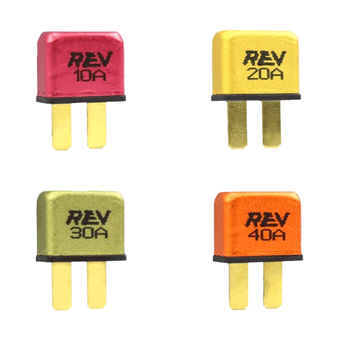
- Breakers and fuses are what gets stuck into the power distribution boards so that your precious and expensive electronics don’t break from a potential voltage overload. They are meant to break the electrical connection after too much electricity is supplied, and thereby saving electronics from undergoing that hit. Fuses are sacrificial and always a one time use while breakers are able to be reused in cases, though they can be popped and be rendered unusable.
- Some components will list what breaker should be used on their website but as a general rule of thumb:
- 10-12 AWG Wire = 40A Breaker
- 13-16 AWG Wire = 30A Breaker
- 16-18 AWG Wire = 20A Breaker
- 22 AWG Wire = 10A Breaker
- REV's Breakers are the best choice.
Main Breaker
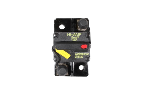
- The main breaker is varied in form and is a crucial part of the robot. It’s basically your robot’s on/off switch. It is required to exist and be accessible on every robot.
- CTRE
- This breaker takes an M6 nut.
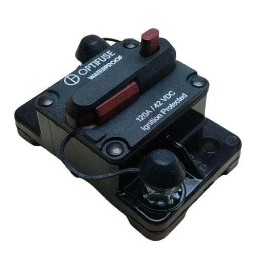
- This breaker takes a ¼-28 nut.
Warning
DO NOT USE OPTIFUSE BREAKERS. They are prone to failures and pop easier than almost any other kind. See this CD thread for more information
RSL (Robot Signal Light)
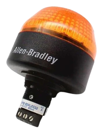
- The RSL is crucial to safety on the robot. It turns on when the robot is powered on and blinks when the robot is enabled.
- Wiring the RSL is relatively simple: Make sure the black wire strand from your two strand wire, or ground is in the middle port labeled N, join the two outer ports with a small piece of red wire, and then in the terminal labeled Lb, place the red wire strand from your two strand wire. For easy replaceability, get the RSL Lever Lock Hub. In both cases, use a small flathead screwdriver for either all wiring or placing the hub in.
Systemcore
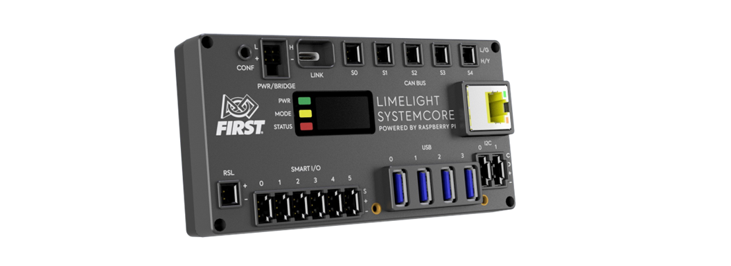
Smaller Power Distribution
These are like the power distribution boards, but they are used for electronics that may need less voltage. They would be used when you don’t have enough spots on your main distribution board.
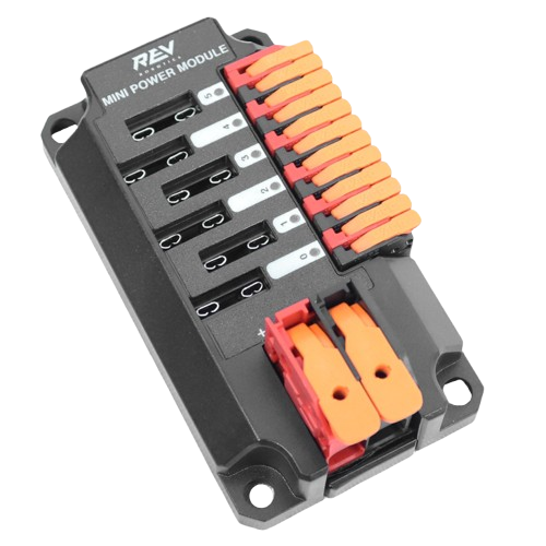
- REV Mini Power Module is commonly used to provide regulated power to smaller electronics and sensors.
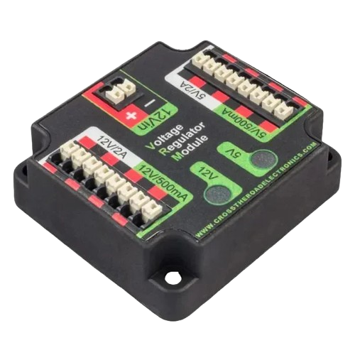
- CTRE's Voltage Regulator Module (VRM) is used when a stable lower voltage supply is needed for supporting electronics.
Cameras
These are for vision processing. They’re important in both autonomous and tele-operated periods of your robot.
- A compact camera option commonly used for custom vision setups.
- Good for teams looking for flexibility and a lower-cost entry point.
Note
Unlike LumaP1 or Limelight, you will need to provide your own coprocessor when purchasing this camera
- LumaP1 is a strong option for teams wanting a modern camera with solid image quality.
- ThriftyCam is a budget-friendly choice for teams looking to keep costs down.
Note
Unlike LumaP1 or Limelight, you will need to provide your own coprocessor when purchasing this camera
- Limelight is a popular quality-oriented choice for FRC vision systems.
Sensors
- CANRange: Sensor that uses proximity to automate. Can be used in intakes or passthroughs to automate movement or running of other components (motors, etc)
- Limit Switch: A switch that is typically wired to the Digital Input/Output (DIO) of the RoboRIO. Used to track the range of a mechanism. The sensor contains a physical material, such as a lever, that is typically over an input (like a button). From there, it can track when the button is pressed.
- This can be used as a hard limit to mechanism movement such as for elevator or pivoting mechanisms.
- Mag Switch: Mag switches are sensors that detect the presence of a magnet. Typically used to track distance, this sensor is usually used to hard-stops on mechanism movements.
- CANandColor: Sensor that is used to track proximity and color. Can be used in games that have two game pieces of different colors (such as 2025 Reefscape™)
- Beam Breaks: Sensor that includes an emitter and receiver. When an object passes through the emitter, a signal is sent to the receiver and this can be used to track the movement of a gamepiece within the robot. Automation can be used in pivoting mechanisms for movement.
- Absolute Encoders: These allow for the rotational accuracy of shafts. This is important for swerve drive accuracy rotationally as well as other precise mechanisms.
- CTRE's CANcoder - Quality Pick
- TTB Magnetic Encoder - Price Pick
Robot Radio 2.0
- VividHosting’s Robot Radio 2.0 (no link yet) is what gets the signal from the driver station to relay information to the robot to make it do all the fun things robots do. Placement of this is especially important and should be done with care.
- The radio should be mounted against a metal tube or plate.
- Heat can build up inside the radio. By mounting the radio against a metal surface, you can conduct heat away, allowing it to disperse.
- Do not block the visibility of the status LEDs.
- The radio should not be fully enclosed by a case or mounting solution.
- This traps heat in the radio and can cause the radio to overheat.
- The radio should be easily removable, as it is programmed for each competition.
- Zipties are a great way to mount your radios.
Tip
When Radio is placed in a specific location with little bearing on where it is placed, such as on pocketed plates, Outline it with a sharpie.