Intro
Safety
This may come as a shock, but electronics are dangerous. A single mistake could lead to serious injury, and it is vital to learn how to follow proper procedure when handling electronics.
- When a battery spills, cover it with baking soda. This neutralizes the battery acid and it becomes less harmful
- Never hold batteries from the wires. Always hold them from the body.
- Always wear PPE when handling electronics. This includes at the bare minimum safety glasses.
- Don’t touch the metals of opposite polarity wires together, especially for batteries as it can cause sparks and flame.
- Don’t allow metal shavings to get into components: Electrical tape open holes.
- Keep wires away from things that can break them like motor splines or the insides of swerve modules.
Electrical Theory
While electrical isn’t overly complex and the theory is rarely used in FRC electrical, a basic understanding is good to know.
Voltage, Current, and Resistance
- The standard definition is the difference in electric potential between two points. However, this is hard to imagine visually. Think of a wire as a pipe, and the electrons flowing through it as water. Voltage would be the water pressure. It is measured in Volts (V), where a higher voltage means more pressure/potential.
- Current, in this analogy, would be the rate at which water flows through the pipe. It is the flow of electrons going through the wire measured in Amps (A).
- Resistance can be thought of as blockages in this pipe or as points where it gets narrow. It is the resistance of the flow of electrons measured in Ohms (Ω) that slows the electrons from getting from point A to point B.
Power vs. CAN
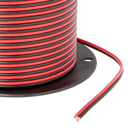
- Power wire is red (for positive terminals) and black (for negative and ground terminals). FRC power wires MUST be color-coded separately, as they can be dangerous when not indicated. Red and black are the most common ways to do so. They can be thought of as the blood vessels that deliver power to every part of the robot.
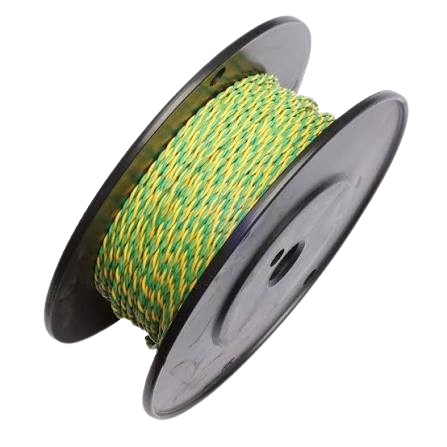
- CAN Wire can be any two colors, but they are most commonly green and yellow. This color scheme can be changed to most anything to differentiate between different CAN buses. CAN is essentially the robot's information system. If the power wires are the blood vessels, CAN is the nervous system.
- Differential Buses: CAN is a differential bus. This means that it essentially transfers information by measuring the voltage difference between two wires in a pair (CAN High (Yellow) and CAN Low (Green)). This makes it more resistant to noise, or electromagnetic interference (EMI), which is prevalent in FRC. However, some measures need to be taken for this noise resistance to be most effective:
- Twist the wire pairs: We do this because it allows any external vibrations and EMI to affect both wires rather than one, keeping the measurements on each wire consistent with each other.
- Strain relief: This is important in any system, whether power or CAN, but it is especially important for CAN wires to reduce noise and vibrations.
- Differential Buses: CAN is a differential bus. This means that it essentially transfers information by measuring the voltage difference between two wires in a pair (CAN High (Yellow) and CAN Low (Green)). This makes it more resistant to noise, or electromagnetic interference (EMI), which is prevalent in FRC. However, some measures need to be taken for this noise resistance to be most effective:
Parallel vs Series
Paralell
- Negative to Negative and Positive to Positive
Series
- Components are chained together from positive to negative to positive, etc.


Parallel Circuit on the left, Series Circuit on the right