Pneumatics
The Pneumatic System works to deliver quick, typically linear, movements using compressed air. While not used in Modern FRC, they are important to learn properly!
They can be very dangerous
This is the general FRC Pneumatics Layout you need to learn:
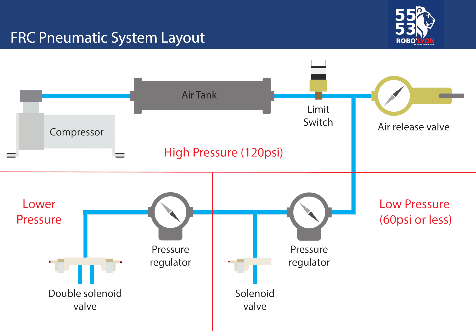
Here are the FRC Pneumatic Components Explained: * Compressor: Charges air for components on the robot, like a battery that provides electricity to components, and the compressor provides air.
-
Pressure Switch: Works with a controller to tell the compressor when to shut off.
-
Solenoid Valves: Electronically controlled valves.
-
Pneumatic Controllers
- PH/PCM: Controls the compressor and up to 8 solenoids. It gains input for a pressure sensor to control the compressor when needed. CAN-based communication
- Pressure Switch: Manages amount of pressure in the robot. Acts as “go-between” for the PCM and compressor.
-
Dump Valve: Releases (or dumps) all air out of the robot.
-
Electrical Solenoid Valve(s): Actuates the different sides of a pneumatic component, such as a shifter or piston. Can be single or double action.
-
Compressor: Charges air for components such as pistons and shifters on the robot. FRC-legal amount of air is 120 psi (pounds per square inch).
-
Emergency Relief Valve: Keeps the air under 125 psi if the compressor or pressure switch is working incorrectly
Be sure to stay safe and use Pneumatics properly!